
This post is going to be a long one, because I need to be thorough and deliberate if I am to be understood; my target audience consists of people who don't know much about computers, and frankly I'm just a dilettante with no formal training on the subject. But disqualification on both ends notwithstanding let's forge ahead and see what comes of it. First, you have probably noticed that computers are everywhere: to use a colorful, if somewhat perplexing, expression, you can't swing a cat without hitting one these days, and when I'm not staring straight into one of my own, I'm probably still using one in some way or other:
But despite their total ubiquity, I don't really know what they are. I certainly couldn't tell you how one works at any significant level of detail. Sure, I put one together in the 6th grade with my stepdad's help, but beyond knowing the names and relative locations of hardware components, I'm as good as clueless w.r.t. how the damn thing operates.
At least, I was until I read “The Elements of Computing Systems” by Nisan and Schocken, whence most of the foregoing figures, and indeed much of the discussion, is derived. This was a great book, and feel like I learned a lot, but I want to confirm my understanding by way of an explanation. So, I propose to explain to you how a computer works. Here goes…
Overview
First some broad strokes: if you haven't ever popped open your computer case, you should know that there's a big flat thing in there—usually green, crisscrossed by circuitry, festooned with ribbony wires, bestudded with various slots and nubbins—to which all else appears attached: it is a breadboard so vital it was christened the “motherboard.” Acting as the spinal cord of the computer, it connects the CPU, the memory, and everything else together.
For brevity, I'm going to limit this discussion to a computer's essentials with little talk of peripheral devices, etc. The CPU, a chip with over a million transistors in one integrated circuit, is where all the magic happens (we will talk about transistors, too). It is responsible for executing program instructions and it generates so much heat thereby that it has its own fan attached to its backside. RAM, a computer's main memory, comes in “sticks” and is used to store the currently executing program and requisite data; typically, RAM (which we will discuss in greater detail below) is wiped in the absence of power. Hard drives, which can store far greater quantities of material over long periods of time, encode data—a string of of binary information like $...01001011...$—as a sequence of differences in magnetization (conceptually, $...+ - + + - + - - ...$). Ugh, I feel like I'm getting ahead of myself, so lets start at the beginning with logic gates.
Logic Gates
Computers take in input and give output based on a decision rule, or many such rules chained together. They use the same logic you'd find in any high school math textbook, in the chapter on probability, near the discussion of sets or Venn diagrams.
The man in this picture is George Boole, and though you have Liebniz to thank for binary numbers, it was Boole's mathematical insights in the mid 1800s that were most foundational to the development of computing, not to be fully realized until some 100 years after his death. You may have heard of Boolean algebra, the variables of which are truth values 1 = TRUE or 0 = FALSE, and the basic operations of which are conjunction (AND), disjunction (OR), and negation (NOT). Think of each operation as taking two inputs and generating an output. For x AND y to equal 1, both x and y must be 1. For x OR y to equal 1, either x or y (or both!) must equal 1. For instance, with AND,
Now imagine that instead you have come up with a tiny device that implements one of these functions (OR, say) with High/Low voltage (say HI/LO) representing 1,0 or TRUE/FALSE. Two wires going into it represent the input, and the one wire coming out represents the output. So if the OR device gets one high and one low voltage input, you get (HI OR LO) = HI, a high voltage output signifying TRUE, which can in turn can be fed into other devices (called “logic gates”) as input. So all you need are physical devices that can implement these Boolean functions by acting as electronic switches… historically, vacuum tubes and transistors etched in silicon have been used for this purpose, but the possibilities are manifold. This is what is meant by “digital” electronics; there are two discrete voltage bands that allow for clean signalling. You can have many different inputs, but only a single output, which can act as the input signal for still other functions.
It gets better: you don't even need AND, OR, and NOT. They can all be constructed from either the NAND function (short for “not and”, it has the opposite output as AND) or the NOR function (“not or” has the opposite output as OR), so actually just a single function can underlie an entire computer. For example, you can implement the OR function, the NOT function, and the AND function using only NAND:
x OR y  = (x NAND x) NAND (y NAND y)
NOT x   = (x NAND x)
x AND y = (x NAND y) NAND (x NAND y)
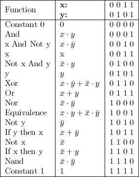
This property is known more technically as functional completeness; every possible logic gate or truth table can be assembled from NAND gates or NOR gates. Below is a complete list of the 16 possible functions for two inputs, x and y. The input values are shown on top, and the output values for each pair of inputs are shown for each function below.
Keep these functions in mind, because we will return to them shortly when we broach the subject of how to implement the arithmetic-logic unit. Before we do this, though, we ought to look a little more at how computers manage to do all of mathematics with just 0 and 1.
Bits and Binary
At least on the face of it, this section should be more familiar: one thing everyone knows about computers is that their “language” is binary, and that it consists of letters called “bits” that can take either of two values, 0 and 1. Though humans find it convenient to represent numbers in base 10 form, computers prefer their information in base 2 (but think, if instead of 5 we had eight fingers on each hand, we'd all be fluent in hexidecimal). For instance, the number 25 would be represented in memory (by a 32-bit computer) as $$(000000000000000000000000000 \mathbf{11001})_2$$ because binary is calculated in base-2 $(2s,4s,8s)$ instead of base-10 $(10s, 100s, 1000s),$
$$ \begin{align} 25 &= ...\mathbf{1}\times(2^4) +\mathbf{1}\times(2^3) + \mathbf{0}\times(2^2) + \mathbf{0}\times(2^1) + \mathbf{1}\times(2^0)\\ &= ... 16 + 8 + 0 + 0 + 1 \\ \end{align} $$
Binary addition is a straightforwardly analogous to base 10 addition: put one number on top of the other, and starting on the right-hand side, add columns like you normally would. If you have a 0 and a 0, put a 0 below the line; if you've got a 0 and a 1, put a 1 below the line. If you get a 1 and and 1, you know 1+1=2, and in binary this means you have to carry, so put a zero below the line and carry a 1 over to the next-right-most column. If you've got a 1 and a 1 and another 1 that was carried over, well, that makes three, so leave 1 under the line and carry once again to the next-right-most column. Here's a picture to illustrate:

So addition makes sense, and because you'll only have three inputs (top bit, bottom bit, and carried bit) you can summarize the operation as follows: if I the top, bottom, and carry bits are all 0, output 0. If one of them is a 1, while the other two are 0, output 1. If two of them are 1, output zero and carry 1 to the next column; If all three bits are 1, output 1 and carry 1 to the next column. All 23 input/output possibilities are shown below:

So we can see that binary addition of two n-bit numbers can be formalized by these simple input/output rules, which can them be effected in material form using logic gates designed to calculate the sum of three bits—a pair of bits plus a carry bit. Good. What about subtraction? If we had positive numbers, we could just pipe those into the “adder”…what about negative numbers? Here's where things get interesting. Though there are many methods of representing negative numbers in computing, the most common by far is one called the “2's complement” or “radix complement” method. It represents a negative number, say $-x$, as $2n-x$. So, say you are using an 8-bit system, and you want to represent -3 (negative 00000011). You go 28-3, which equals 253, which is 11111101 in binary. The reason for doing it this way is that 00000011 + 11111101 = (1)00000000. Below is a table showing the first few positive/negative integers in a 4-bit system. Notice that all negative numbers begin with 1, whiel all positive numbers begin with 0. In general, if you have x and want to know -x, leave all of the trailing zeros and the first 1 intact, but flip the values of all the rest.

The arithmetic-logic unit (ALU) is the centerpiece chip that executes all the arithmetic and logical operations performed by the computer, but you may not have heard of it. That's because we typically just talk about the central processing unit (CPU), which includes the ALU, a set of local registers, and a control unit. The control unit has a switchboard-type task; it must decode instructions and use the information to signal the various hardware devices (ALU, registers, etc.) how to execute the instruction. The CPU operates in a continuous loop known as a fetch-execute cycle: fetch an instruction from memory, decode it, execute it… fetch the next instruction, decode it, execute it… Instruction execution could be “have the ALU compute some value”, “copy the contents from register 13 to register 14”, “write a word to memory”, etc…
The ALU, though, is where the rubber meets the road; it is responsible for computing elementary operations using a more complicated version of the addition chip (“Full Adder” in the figure above). I'm going to describe for you an efficient, completely functional ALU with two 16-bit inputs $(x,y)$ and one 16-bit output $(out)$ that is capable of computing a fixed set of arithmetical or logical functions $(f)$, where $out = f(x,y)$.

We tell the ALU which function to compute by setting six input bits, called control bits, to selected binary values (top of the figure above). These settings specify the following logical steps which carry out the function they encode (see big figure below).
$$ \begin{align} if \ \ (zx = 1) \ &then \ (x = 0) \phantom{xxxxxxxxx..} (e.g., \ 11001101011010111 \rightarrow 0000000000000000) \\ if\ \ (nx = 1) \ &then \ (x = NOT \ x) \phantom{xxxxxx}(e.g., \ 0000111100001111 \rightarrow 1111000011110000) \\ if\ \ (zy = 1) \ &then \ (y = 0) \\ if\ \ (ny = 1) \ &then \ (y = NOT \ y) \\ if\ \ (f = 1) \ &then \ (out = x+ y) \phantom{xxxxxxxxxx.} \text{(binary addition as we described it above)}\\ if\ \ (f = 0) \ &then \ (out = x \ \& \ y)\phantom{xxxxxxxxxxxxxxxxxxxxxxxxxxxxx} \text{(AND operation)} \\ if\ \ (no = 1) \ &then \ (out = NOT \ out) \\ if\ \ (out = 0) \ &then \ (zr = 1, else \ zr = 0)\phantom{xxxxxxxxxxxxxxxxx} \text{(tests if the output is zero)} \\ if\ \ (out \lt 0) \ &then \ (ng = 1, else \ ng = 0)\phantom{xxxxxxxxxxxxx.} \text{(tests if the output is negative)} \\ \end{align} $$
The table below is confusingly arranged, but it actually contains the values that each control bit should be set at to achieve a given function (the far right column).
Let's walk through one, just to see. Say our data inputs are
$$ \begin{align} x &= 0000001111101000 \ \ \ \text{ (the number 1,000 in base-10)} \\ y &= 0000000001111011 \ \ \ \text{ (the number 123 in base-10)} \\ \end{align} $$
…and we want to compute x - y. We could find the settings for our control bits by going to to far right column (“Resulting ALU output”), locating x - y, and reading off the settings for our six control bits listed in the row (zx = 0, nx = 1, zy = 0, ny = 0, f = 1, no = 1). Since zx = 0, we do not zero the x input. Because nx = 1, we do switch all of the bits around in x. now we have
$$ x = 1111110000010111 $$
We don't have to zero the bits from the y input because zy = 0, nor do we have to switch them around (ny = 0). The next control bit, f = 1, tells us to compute x+y (using something like the “Full Adder” above).
`$$ \begin{array}{c c} & 1111110000010111 \
- & 0000000001111011 \
\hline & 1111110010010010 \
\end{array} $$`
Finally, because no = 1 we have to flip all the bits of the output. Doing so results in the following:
$$ 1111110010010010 \rightarrow 0000001101101101 $$
…which is the number 877 in the base-10 system (1000 - 123 = 877). In this way, our ALU is able to compute all of basic arithmetical operations (the one in your computer does essentially the same thing). You could, if you which, verify that this is true for the other operations by setting your control bits according to row of interest, but I assure you that it works out. Our ALU lacks support for multiplication, division, floating point arithmetic, etc., but these operations can be implemented on top of the hardware at the level of the operating system.
Tick-Tocks, Flip-Flops
So far, we have been processing information, computing functions based on different combinations of input. But then what? How is it stored? As it stands, a logical function is performed and poof, the result is gone. Computers have to maintain state; they have to preserve data over time; they have to remember. Such memory elements are built from sequential chips. Let us now talk about tick-tocks and flip-flops, yes I mean timekeeping and no, not the footwear.
Most computers have a master clock that delivers a continuous oscillating signal, a “tick” and then a “tock”, which together constitute a cycle. These ticks and tocks are represented by a binary signal ($...1...0...1...0...$) which is broadcast throughout the computer.
OK, now flip-flops; get excited, because if you thought logic gates were cool, you're going to flip-flop your shit here. Flip-flops are the mechanical incarnation of memory. All they do is take their input at $time = t$ and output it at $time= t+1$; the magic of this is that you can feed the output at $time= t+1$ back into the input at $time = t+2$. If nothing has been changed (no new inputs to consider), then the value is maintained in a continuous cycle of inputs and outputs… through this recursion, the information is preserved over time. What I've just described is actually a register, but the flip-flop is the central component. Have a look at the image below. Say we ask this 1-bit register to remember the value 1 for a while; our in is 1, and it gets loaded into the flip-flop (DFF in the figure). If we don't give the register any new inputs, then it remembers 1 in an infinite cycle of output 1, input 1, output 1, input 1… to the beat of the master clock's metronome. Recognize how important this idea is: registers, memory counters… they are all based on flip-flops! How many GHz is your processor? My laptop says 2.9GHz…which is to say, almost three billion tick-tock/flip-flops per second!
Now that we have a way of remembering a single bit over time, we can remember much more information by putting many such single-bit registers side-by-side in an array. Stack 8, 16, 32, or 64 such 1-bit registers together, and you've got a multi-bit register. Say we need to hold the integer 14 in memory: we could send 00001110 to an eight-bit register (a byte) and each 1-bit register would be responsible for remembering the value it was assigned.
While computers typically work with multiple-bit quantities at the same time (ASCII text characters like these are each 8 or 16 bits long; screen pixels and floating-point numbers can be up to 32 bits long), amazingly, much data gets sent and received literally bit by bit: I/O devices like keyboards, mice, printers etc.; even USB and Firewire (“serial ports”) transfer just one bit at a time.
Stack a bunch of these multi-bit registers together, and you've got RAM. Sort of. Because now that there's so many bits being stored, how are you ever going to find the ones you need? Fortunately, each memory register is given a unique address according to which it can be accessed. RAM takes three inputs: the data input, the address, and a load bit (if you just want to “read” the register, then the load=0; if you want to “write” a new value to the register, load=1). The schematic to the left is misleading: the size of each “register” in your RAM is 32- or 64-bits wide, and there are hundreds of millions of them!
Even if we ask nicely, all these NAND gates and flip-flops aren't just going to stand at attention, receive their orders, and happily do our bidding; we have to specify precisely what it is we want the hardware to do, and for that we need “machine language”. Let's say we've got a 16-bit computer and we want to tell it something. We'd use an instruction like 1010000110010011; at first blush, it would never occur to us that this string could mean “add the contents of register 1 to the contents of register 9 and store the sum in register 3”. But it could! Each instruction like this one could consist of 4-bit fields, and each field could have a distinct function. The first field could specify an operation, like ADD or AND, the second and third fields could specify input registers, and the final field could specify the output register. If the operation “ADD” has been given the code “1010”, then it is clear what this string is instructing.
$$ \begin{array}{c | c | c | c } add®1®9®3\\ \hline 1010&0001&1001&0011\\ \end{array} $$
To be sure, this example is quite simplistic: if you only had four bits with which to specify the address of a register, you could only have a maximum of $2^4=16$ addresses in memory! Your computer, the one you're using now, has billions! But, for illustrative purposes this is gist of machine language. It's got computation instructions, location/destination instructions, and jump instructions (which tell it what to do next).
I/O
No discussion of computers would be complete without at least superficial coverage of some input/output devices, the two most necessary of which are the screen and the keyboard. The screen, a very visible and impressive part of any computer, is deceptively basic hardware-wise. This is especially true if we stipulate, for our explanation, a few simplifying assumptions, like that the monitor is black and white. Let's also go ahead and say that your computer is a 16-bit computer, and that your resolution is really, really bad (say $512 \times 256$); now, I want you to imagine 512 columns, each containing 256 pixels. Equivalently, you could think of 256 rows, each comprising 512 pixels. Either way, you've got a total of 131,072 pixels in the screen. Each row of pixels in the physical screen, starting in the top left corner, is represented in memory as 32 consecutive 16-bit “words”, and each one of these 16 bits controls a single pixel. Since the size of each “register” in your computer's RAM is 16 bits, there are $32 \times 256 = 8192$ consecutive RAM “registers” that correspond sequentially to the pixels row by row from top-left to bottom-right. Because of a technique called memory-mapped input/output, the pixels on the screen are a direct mapping of the binary values stored in memory: each bit corresponds to a specific pixel on the screen; a given pixel is lit up if its value in memory is 1, and dark if its value is changed to 0. This mapping is made to continuously reflect the physical state of the hardware, so as I type “this”, a bunch of bits in RAM suddenly do something like this (squint at it)
111111111110111111001111111110111111111111111111111111111111
111111111110011111101111111111111110001111111111111111111111
111111111000000111101001111100111101111111111111111111111111
111111111110011111100110111110111110001111111111111111111111
111111111110010111101110111110111001110111111111111111111111
111111111111001111001110011100011110001111111111111111111111
which is mirrored in turn by the lighting of the pixels in the screen. Keyboards are even simpler in principle; each time a key is pressed, the ASCII code corresponding to the requesting character appears in a spot in memory reserved for keyboard input.
There is so much more to know about computers, but I am coming perilously close to the edges of my own understanding. Like I said, I'm a total layman with this stuff, writing for a hypothetical audience of people just like me-before-I-had-read-an-informative-book-on-the-subject. I may add more to this later, but I'm done for now. Actually, I had written more, but Blogger's blasted auto-save screwed me hard and overwrote everything to whitespace somehow, so I want to go ahead and publish before it decides to do it again. I hope I have been able to give you some small insight into these things that are destined to determine, and possibly become, our future.